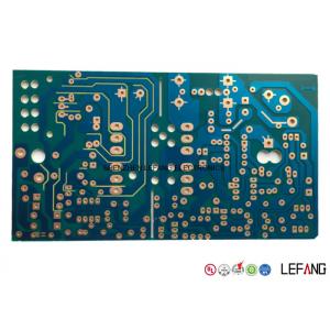
Single Sided PCB for Power Bank Power Supply Circuit Board
The single sided power bank PCB Board is built with 22F raw material, with 1.6 mm board thickness. The size of this 1 layer PCB board is 8 * 80 mm, with blue solder mask and osp surface treatment. The minimum aperture is 0.4 mm. We offer you ODM or OEM service of consumer electonics applications.

How to get quick quotation?
| Step 1 Please send us Gerber file with these format: .CAD / .Gerber / .PCB / .DXP / .P-CAD, etc |
| Step 2 Also please provide us the below details for quick quotation: |
|
Board material: Fr - 4 / CEM - 1 / CEM - 3 / 22F / Fr - 1 / others
|
| Material brand: SY / KB / Rogers (optional) |
| Material Specification:High Tg / copper based / aluminum based or others (optional) |
| Board thickness: 0.1 - 6.0 mm |
| Copper thickness: 0.05 Oz - 8 Oz ( 17 um - 288 um ) |
| Surface Treatment: OSP / ENIG / HASL / Lead Free HASL / Immersion Tin / Immersion Sin |
| Color of solder mask and silk print: Green / red / blue / black / white / yellow ,etc |
| Board size and quantity |
|
If you don't have Gerber file, please provide us the imfomation as step 2 or post your PCB Board to us for clone.
|
|
SAMPLE:
|
|
Board Basic Info - SAMPLE
|
|
Board material
|
Fr - 4
|
|
Material brand
|
KB
|
|
Material Specification
|
Tg 170
|
|
Board thickness
|
1.6 mm
|
|
Copper thickness
|
1 Oz
|
|
Surface Treatment
|
ENIG
|
|
Solder mask / sSilk print
|
Green / White
|
|
Board size
|
100 mm * 100 mm
|
|
Quantity
|
10k
|
|
Technical Data
|
No.
|
Item
|
Data
|
| 1 |
Layer count |
1-20 layers
|
| 2 |
Raw material type |
Halogen free FR-4, high Tg FR-4, thick copper FR-4, CEM-3, copper
based, aluminum based
|
| 3 |
Raw material brand |
Rogers,Isola,Arlon, ITEQ, Hitachi, SY, KB,etc |
| 4 |
Board thickness |
0.1-6.0mm |
| 5 |
Max board size |
600 mm * 700 mm |
| 6 |
Solder mask |
Green, red, blue, black, white, yellow |
| 7 |
Surface treatment |
HASL/HASL lead free , OSP, Immersion gold / silver / tin , gold plating
(hard gold and soft gold), silver plating, tin plating, platinum plating,
carbon ink, and ENEPIG(electroless nickel - electroless palladium -
immersion gold)
|
| 8 |
Copper thickness |
0.05 Oz - 8 Oz (17 um-288 um ) |
| 9 |
Min Line width /space |
0.065 mm / 0.065 mm |
| 10 |
Finished hole size |
0.10 - 5.95 mm |
| 11 |
Blind/buried via |
0.10 mm |
| 12 |
Aspect ratio |
10:1 |
| 13 |
PTH tolerance |
+ / - 0.05 mm |
| 14 |
Hole location tolerance |
+ / - 0.05 mm |
| 15 |
Impedance control tolerance |
+ / - 8% mm |
| 16 |
Outline tolerance |
+ / - 0.10 mm |
Lead Time
| Layer count |
Sample lead time/workday |
Batch lead time/workday |
| 1-2L |
2 |
6 |
| 4L |
5 |
8 |
| 6L |
5 |
9 |
| 8L |
6 |
10 |
| 10L |
8 |
10 |
| 12L |
8 |
12 |
| 14L |
10 |
15 |
| 16L |
10 |
18 |
| 18-40L (Up to difficulty) |
at least 18 |
at least 24 |
| P.S. For HDI, Blind/Buried Hole PCB: Regular Lead Time + 3 workdays |
How many advanced automated equipments do we have?
-- We have spent massively on purchasing below advanced automated production equipments.
| Equipment Name |
Plant in Shenzhen |
Plant in Dongguan |
| CCD exposure machine |
8 |
12 |
| AOI test machine |
6 |
8 |
| Mechanical drilling rig |
26 |
53 |
| Automatic edge finishing machine |
2 |
2 |
| Pressing machine |
2 |
2 |
| VCP |
0 |
2 |
| Electroplating line |
1 |
2 |
| CNC routing machine |
12 |
12 |
| Automatic tester |
10 |
16 |
Now send us your inquiry, and you will be replied within 8 hours!
Little knowledge - Multilayer PCB Board
Multilayer printed circuit boards (Multilayer PCBs) represented the next major evolution in fabrication technology.
A very sophisticated and complex methodology came from the base platform of double sided plated.
This methodology would again allow circuit board designers a dynamic range of interconnects and applications.
Multilayer PCB board were essential in the advancement of modern computing, and their basic construction and fabrication are similar to micro chip fabrication on a micro size.
The range of material combinations is extensive from basic epoxy glass to exotic ceramic fills, and it can be built on ceramic, copper, and aluminum. Also, blind and buried vias are commonly produced in multilayer pcb manufacturing, along with pad on via technology.